![]()
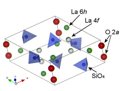
Fig.1 Structure of Apatite-type Lanthanum Silicate
Motivation
Apatite ionic conductors (rare earth silicates) were first found by Nakayama
et al. in 1995 [1,2]. Early studies have revealed that there are many interesting characteristics in these materials. The most important one, however, is their ionic conductivity. They show fairly high ionic conductivity in an intermediate temperature range of 500-800° C [3]. In addition, they have ionic tranport numbers which are very close to
1.0 with a wide oxygen partial pressure range [4], thus being considered as candidates for intermediate temperature solid
oxide fuell cell (IT-SOFC) electrolytes. Another intersting characteristic
is their unique conduction mechanism. They show an interstitial conduction
mechanism with their ionic conductivity enhanced by excess oxide ions.
The ionic conductivity of lanthanum silicate reported by Nakayama et al.
[3], however, was still low (10-20 mS cm-1) for the SOFC application, thus we have started the research to enhance the conductivity.
Two strategies to enhance the ionic conductivity of the apatite-type lanthanum
silicate:
In the unit cell structure of the apatite-type lanthanum silicate in Fig.1, there are six isolated SiO4 units and two kinds of the La site, 6h and 4f, and two oxide ions, 2a,
lined up parallel to c-axis. Normally there are some vacancies in the La
4f site; 1/6 vacancy in this site yields the oxygen-stoichiometric composition
of La9.33(SiO4)6O2 = La9.33Si6O26. The La content can be increased up to near 10 by filling the La vacancy,
then the composition is La10Si6O27 including one excess oxide ion per unit cell [5]. We have evidently shown that an increase in the La content, ie an increase
in the excess oxide ions results in an increase in the ionic conductivity
showing a maximum at the La content of 10 as shown in Fig. 2 [6].
Fig.2 Variation of the ionic conductivity measured at 800 °C with the
La content
Another enhancement mechanism is doping. The conductivity enhancement by
Al doping was first found by Abram et al. [7], followed by the doping studies showing slight enhancements by Ga [8] and B [9], but we have revealed that Mg doping into the Si site is much more effective
[10], [11], [12]. The bar charts in Fig.3 summarize the enhancements of ionic conductivity of lanthanum silicates measured at 800 °C. As the La content increases from 9.33 to 9.67 and 10, the conductivity goes up from 0.59 to 7.1 and 32 mS cm-1due to the enhancement by the excess oxide ions. On the other hand, Al
or Mg doped samples showed 18 and 44 mS cm-1 even without the excess oxide ions. We can use two enhancement mechanisims
at the same time, giving 88 and 74 mS cm-1 at 800°C for La10Si5.8Mg0.2O26.8 and La9.8Si5.7Mg0.3O26.4, respectively [13]. These values are the highest among those reported so far for lanthanum
silicate based apatites.
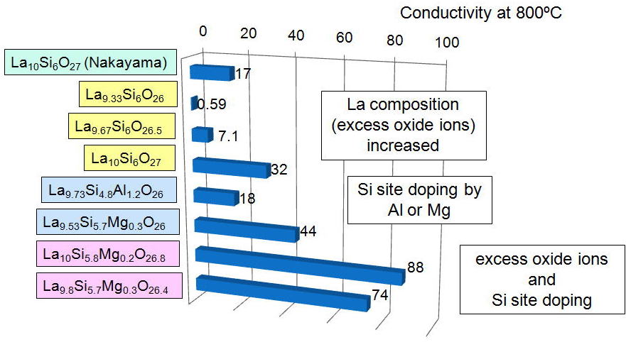
Fig.3 Enhancements of the ionic conductivity by excess oxide ions and doping
Temperature dependence
Fig. 4 shows temperature variation of the ionic conductivity of apatite-type
ionic conductors and other ionic conductors (YSZ and LSGM) as an Ahrrenius
plot [13]. It is revealed that an increase in the excess oxide ions not only enhances
the conductivity but also lowers the activation energy down to a very low
level of 0.43 eV. The conductivity of La10Si5.8Mg0.2O26.8 is higher than YSZ below 800°C and even comparable to LSGM below 550°C.
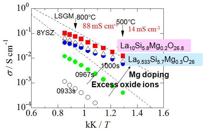
Fig.4 Temperature dependence of ionic conductivity
Structure analysis
We have made structure analysis in order to elucidate the conduction enhancement
mechanism. By the cooperative research with Dr. Ali and Prof. Yashima et
al. [14], we have successfully visualized the nuclear density distribution of
La9.69Si5.7Mg0.3O26.24 from the neutron powder diffraction data measured at 1558°C and MEM-Rietveld
analysis. The interstitial position of the excess oxide ion O5 is determined
at 12i (0, 0.22, 0.65), which connects a channel oxide O4 and a tetrahedron
member O3. We can clearly see two oxide diffusion pathways; -O4-O4-O4-
direct diffusion path parallel to c-axis and -O4-O5-O3- diffusion path
perpendicular to c-axis.
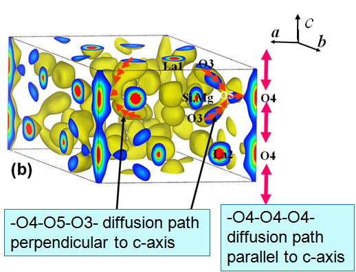
Fig.5 Nuclear density distribution map of Mg-doped lanthanum silicate
Another result on the structure analysis is migration channel size analysis.
Mobile oxide ions migrate parallel to c-axis through La1 triangles and
O3 oxide ion triangles as shown in Fig. 6. We have calculated these triangle
sizes as the migration channel sizes. The results have revealed that the
La1 channel size decrease with the excess oxide ions, whereas Al or Mg
doped samples have the larger O3 channel size [12]. We consider that the O3 channel size affects the mobility of mobile oxide
ions.
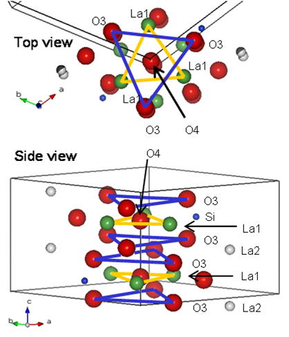
Fig. 6 Diffusion path in apatite conductors
Fuel cell properties
Though the apatite-type oxide ion conductors are considered as IT-SOFC
electrolytes, there are very few papers reporting the fuel cell properties
of the compounds. We believe that the first paper describing the fuel cell
properties as shown in Fig. 7 were published by our group in 2005 [11]. Using a dense sintered disk of Mg doped lanthanum silicate as an electrolyte
and Pt paste for both electrodes, a maximum power density of 20 mW cm-2 was obtained. This value was fairly small, but what is the most important
in this experiment is the open circuit voltage is very close to the theoretical
value, which shows the compound is stable both at oxidized and reduced
atmospheres at these temperatures.
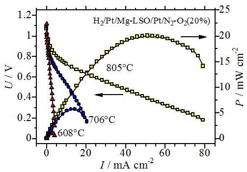
Fig. 7 Fuel cell properties of SOFC using Mg-doped lanthanum silicate as
an electrolyte and Pt paste electrodes
Fuel cell properties are under rapid improvements. In 2008, we have observed
the maximum power density of 125 mW cm-2 at 800°C as shown in Fig.8 using a highly conductive electrolyte,
a Ni-SDC cermet anode and a LSCO mixed conducting cathode [13]. Very recently Dr. Mineshige has observed the maximum power density of 250 mW cm-2. The fuel cell performance is increased, in additon the long-term stability
and reactions with electrodes is evaluated at the same time.
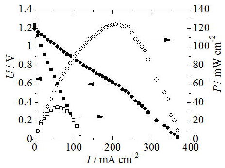
Fig. 8 Fuel cell properties of SOFC using Mg-doped lanthanum silicate as
an electrolyte and NiO anode and LSCO cathode
References
[1] S. Nakayama, H. Aono, Y. Sadaoka, Chem. Lett.,6, 431-432 (1995)
[2] S. Nakayama, Y. Sadaoka, J. Mater. Chem., 5, 1801-1805 (1995)
[3] S. Nakayama, M. Sakamoto, J. Euro. Ceram. Soc., 18, 1413-1418 (1998)
[4] H. Arikawa, H. Nishiguchi, T. Ishihara, Y. Takita, Solid State Ionics,
136-137, 31-37 (2000)
[5] S. Tao, J. T. S. Irvine, Mater. Res. Bull., 36, 1245-1258 (2001)
[6] H. Yoshioka, J. Alloys. Compounds, 408-412, 649-652 (2006)
[7] E. J. Abram, D. C. Sinclair, A. R. West, J. Mater. Chem., 11, 1978-1979 (2001)
[8] J. E. H. Sansom, J. R. Tolchard, P. R. Slater, M. S. Islam, Solid State
Ionics, 167, 17-22 (2004)
[9] A. Najib, J. E. H. Sansom, J. R. Tolchard, P. R. Slater, M. S. Islam,
Dalton Trans., 3106-3109 (2004)
[10] H. Yoshioka, Chem. Lett., 33, 392-393 (2004)
[11] H. Yoshioka, S. Tanase, Solid State Ionics, 176, 2395-2398 (2005)
[12] H. Yoshioka, J. Amer. Ceram. Soc., 90, 3099-3105 (2007)
[13] H. Yoshioka, Y. Nojiri, S. Tanase, Solid State Ionics, 179, 2165-2169
(2008)
[14] R. Ali, M. Yashima, Y. Matsushita, H. Yoshioka, K. Ohoyama, F. Izumi,
Chem. Mater., 20, 5203-5208 (2008)
![]()